Speed sensors of type FA52 are non-contacting one- or two-channel speed sensors with a stainless-steel flange and sensor tube. They measure frequency in accordance with the Hall effect principle. They acquire the speed of ferromagnetic gearwheels, e. g. gearwheels with various tooth shapes, screw heads, drill holes, apertures, grooves or pulse bands on smooth shafts (accessories). Their compact and robust design, as well as the relevant tests as per DIN EN 50155, make them ideal for applications in the field of transport technology, e. g. measuring speed at the traction motor, gearbox or wheelset. The sensors are available with different output signals (voltage or current output).
Unless stated otherwise, the sensors mentioned here have voltage signal outputs.
Type | Signal outputs | Signal waveform |
|---|
FAH52
FAHJ52 | A square wave signal;
FAH: Voltage signal output
FAHJ: Current signal output | 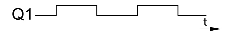
|
FAHZ52
| Two square wave signals,
Q2 to Q1 phase offset by 90° | 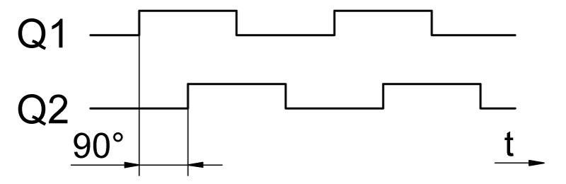
|
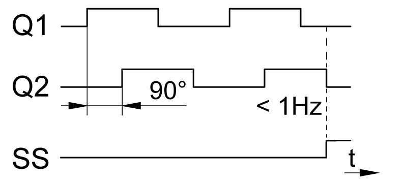
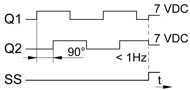
FAHS52 | Two square wave signals,
Q2 to Q1 phase offset by 90°, and - a direction of rotation signal
- or a stillstand signal
- or a 7 V status level of Q1 and Q2 during outage (~medium voltage)
- or a 7 V status level of Q1 and Q2 during outage (~medium voltage) and an additional stillstand signal output
| Direction of rotation:
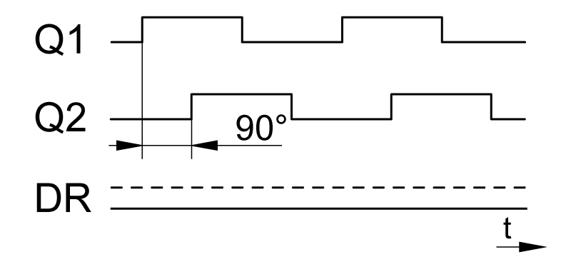 Stillstand signal: Stillstand signal:
 Medium voltage: Medium voltage:
 Medium voltage + stillstand signal: Medium voltage + stillstand signal:
 |
FAHI52
FAHD52 | Two galvanically isolated square wave signals
Q2 to Q1 phase offset by 90°,
type FAHD with voltage signal output,
type FAHI with current signal output | 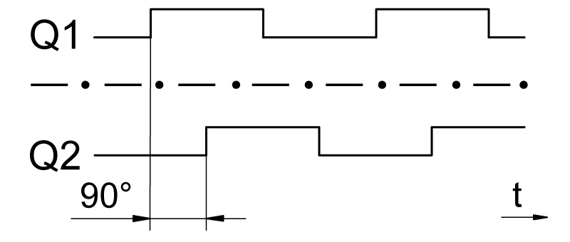
|
FAHQ52 | Two square wave signals + two inverted square wave signals, Q1 to Q2 and <emphasis type="NGRNegation">Q1</emphasis> to <emphasis type="NGRNegation">Q2</emphasis> phase offset by 90° | 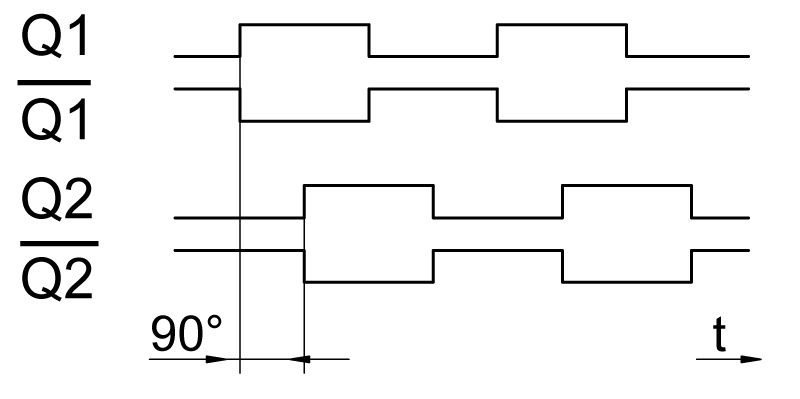
|
