Speed sensors of type FA11 are non-contacting one- or two-channel speed encoders with a brass threaded tube. They measure frequency in accordance with the difference-hall-effect principle (FAH type) or inductive-magnetic principle (FAJ type). These speed sensors are suitable for scanning ferromagnetic materials, e.g. gearwheels with various tooth shapes, screw heads, drill holes, apertures, grooves or pulse bands on smooth shafts (accessories). Its compact and robust design, as well as the relevant shipbuilding approvals, make this product ideal for marine applications.
Type | Measuring principle | Output signals | Signal pattern |
|---|
FAH11 | Difference-hall | 1 square wave signal | 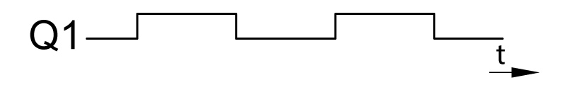
|
FAJ11 | Inductive magnetic | 1 square wave signal |
|
FAHZ11 | Difference-hall | 2 square wave signals,
Q2 to Q1 90° phase offset | 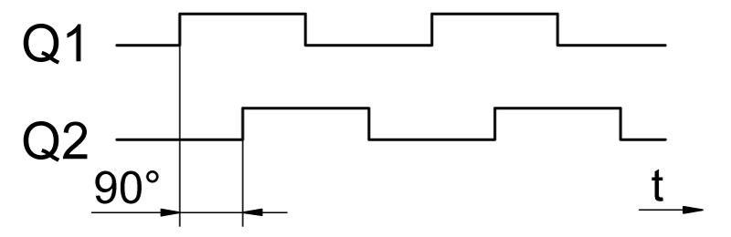
|
FAHS11 | Difference-hall | 2 square wave signals,
Q2 to Q1 90° phase offset,
1 status signal for rotational direction detection | 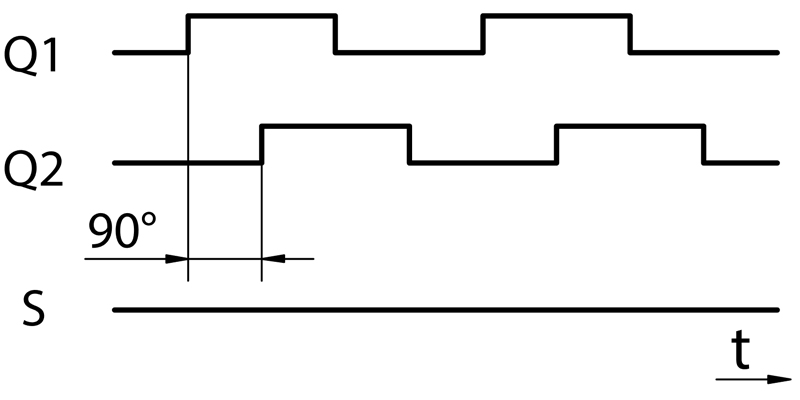
|
FAHD11 | Difference-hall | 2 square wave signals,
Q2 to Q1 90° phase offset,
signals galvanically isolated | 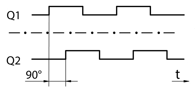
|
Approvals | |
|---|
| FAH11 | FAJ11 | FAHZ11 | FAHS11 | FAHD11 | FAHQ11 |

| X | X | X | X | X | X |

| X | X | X | X | X | X |

| X | X | X | X | X | X |

| X | X | X | X | X | X |
